


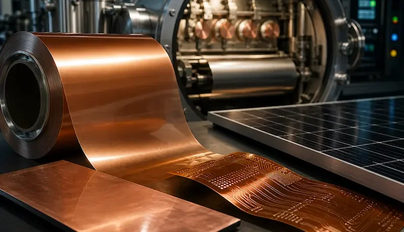
Copper-Coated Films for PV Backsheets and EMI Shielding
Two industries keep pushing film makers toward the same material: solar module manufacturing and electronics protection. In a solar module, a conductive layer collects current and reflects light. In electronics, a conductive layer blocks the electromagnetic interference that would otherwise corrupt signals. In both cases, copper-coated film does the job.
Copper-coated film pairs a polymer carrier — usually PET — with a thin, highly conductive copper layer. Consequently, it delivers conductivity, flexibility, and low weight in one material. In this guide, we explain why copper wins, how coating lines produce the film, how it performs in PV backsheets and EMI shielding, and what to check before you buy.
Why Copper? The Conductivity Case
Copper ranks as the most conductive common metal after silver. Its resistivity of roughly 1.68 × 10⁻⁸ Ω·m beats aluminum’s 2.82 × 10⁻⁸ Ω·m by about 40%. Therefore, a copper layer carries more current and reflects more electromagnetic radiation than an aluminum layer of equal thickness.
Copper brings two further advantages. First, it tolerates repeated flexing without cracking, which matters for flexible circuits and roll-to-roll processing. Second, it solders easily, so assembly teams can attach components without special chemistry. However, copper tarnishes in air, so a copper-coated film usually needs a protective layer or a controlled environment. Aluminum forms a natural passivating oxide, but it cannot match copper’s conductivity.
How Coating Lines Produce Copper-Coated Film
Copper melts near 1,085 °C, so simple thermal evaporation from a boat struggles with it. Instead, manufacturers rely on two vacuum methods:
- Magnetron sputtering — energetic ions knock copper atoms off a target, and those atoms settle onto the moving web. Sputtering handles copper’s high melting point well and controls thickness precisely.
- Electron-beam evaporation — an electron beam heats copper in a crucible until it vaporizes onto the web.
In practice, many lines combine both approaches with other steps. A vacuum-deposited copper layer can act as a seed layer for electroplating when an application needs thicker copper. Meanwhile, roll-to-roll platforms keep the web moving under tension, so the process coats hundreds of meters in one pass. For a technical comparison of these methods, see our article on vacuum metallizing, magnetron sputtering, and CVD.
Copper-Coated Film in PV Backsheets
A PV backsheet protects the module from moisture, ultraviolet light, and mechanical damage, and it provides electrical insulation. Beyond that protective role, some module designs make the backsheet conductive.
Back-contact and metal-wrap-through (MWT) modules use a conductive backsheet that carries a patterned copper circuit to connect cells. This design connects MWT solar cells in series without the soldered ribbons that traditional strings require, which reduces shading and improves yield. Copper’s conductivity makes it the natural choice for that circuit.
Copper-coated film also contributes in three supporting roles:
- Light management: a reflective copper surface bounces light back toward the cells, which raises output.
- Barrier protection: a metallic layer slows moisture ingress that degrades encapsulation.
- Lightweight, flexible modules: a thin copper layer supports portable and building-integrated solar products that cannot carry heavy glass and foil.
One honest note matters here. A circuit that carries full module current usually needs copper foil or plated copper, because a sub-micron vacuum layer cannot move that much current. Therefore, vacuum coating supplies the thin conductive and barrier layers and the plating seed, while the heavy current path stays with thicker copper. Because a conductive backsheet must also survive lamination and decades outdoors, film makers tune both the copper layer and the polymer stack together. Industry analysts note that integrating copper-coated films into PV backsheets promises higher module efficiency and new revenue for suppliers.
Copper-Coated Film for EMI Shielding
EMI shielding stops electromagnetic energy from entering or leaving a device. A conductive film reflects most incoming radiation, because free electrons in the metal re-radiate the incoming wave. Copper’s high conductivity makes it one of the strongest reflectors available, so electronics makers commonly choose copper coatings for shielding.
Engineers measure performance as shielding effectiveness in decibels (dB):
- 20 dB removes about 99% of the signal power.
- 40 dB removes about 99.99%.
Published research on package-level shielding reports values from roughly 12 dB to 55 dB across different frequencies and materials, which shows how much frequency and thickness shift the result.
Frequency also decides how thick the copper must be, because current concentrates near the surface. At 1 GHz, the skin depth in copper measures about 2 µm, so a thin layer shields well. At 1 MHz, the skin depth grows to roughly 65 µm, so the same thin layer shields magnetic fields poorly. Consequently, thin copper-coated film suits radio-frequency shielding in phones, flexible printed circuits, and cable wraps, while low-frequency magnetic shielding demands thicker or magnetic materials. Manufacturers widely use copper and aluminum coatings as shielding options for exactly these reasons.
Copper-Coated Film vs Copper Foil and Other Conductors
Copper-coated film and copper foil share the same metal, yet they serve different jobs. The film wins wherever thinness, weight, and flexibility matter; the foil wins wherever the conductor must carry heavy current.
What a Coating Line Must Deliver
Coating copper onto film rewards precision, because a weak layer fails later in a costly assembly. Therefore, buyers should weigh these capabilities:
- Copper deposition capability — magnetron sputtering or electron-beam evaporation, not a standard aluminum boat.
- Uniform deposition across the width — variation across the web shifts sheet resistance from part to part.
- Gentle web handling with stable tension — thin PET webs wrinkle and stretch, which disturbs conductivity.
- Surface preparation for adhesion — a treated surface keeps the copper bonded through converting.
- Oxidation protection — a passivation or protective layer preserves conductivity in storage and use.
- Inline resistance monitoring — closed-loop control holds the layer on target roll after roll.
A platform such as Tempo Machinery’s fully automatic suspension vacuum coating machine brings a free-suspension web path, double coating-drum cooling, online OD detection, a Siemens PLC, and four servo motors that hold constant tension. Our sputtering capability extends the metal range to copper and other high-melting-point materials. In practice, our standard machines cover 6–150 µm, so we always recommend discussing your exact film and target resistance with our engineers before you order.
Quality Checks That Decide Performance
Both markets judge the film on function, not appearance, so quality control targets conductivity and durability.
Because adhesion and pinholes cause most field failures, our guides to adhesion testing for metallized film and vacuum coating defect troubleshooting help operators set practical limits.
Market Outlook for Copper-Coated Films
Demand tracks both end markets. Published estimates vary widely with scope, which is worth noting before you cite a single number. MarkWide Research values the copper coated films market at $892.4 million in 2026 and projects $2,053.1 million by 2035 at a 9.70% CAGR, while Future Market Insights (reported via openPR) puts the copper coated film market at $3.32 billion in 2026, growing to $4.77 billion by 2036 at a 3.7% CAGR.
The drivers stay consistent across reports. Electronics miniaturization pulls flexible printed circuits toward thinner copper, and analysts also point to copper-coated films in PV backsheets and printed antennas as growth areas. Meanwhile, the shift toward flexible and lightweight solar products keeps expanding the conductor’s role.
Conclusion
Copper-coated film gives manufacturers a thin, flexible, highly conductive layer for two demanding jobs: PV backsheets and EMI shielding. Copper out-conducts aluminum, and a vacuum-deposited layer stays thin enough for flexible products. However, the material demands sputtering or electron-beam capability, uniform deposition, and protection against oxidation. Therefore, choose equipment built for multi-metal precision, and verify sheet resistance and shielding effectiveness before you commit to volume production.
Ready to evaluate a coating line for copper-coated film? Contact our team for machine specifications, customization options, and a free consultation on your coating requirements.
FAQ
1. Why use copper instead of aluminum for a conductive film?
Copper conducts about 40% better than aluminum, so it carries more current and reflects more radiation at the same thickness. Aluminum costs less and resists corrosion naturally, yet copper wins wherever conductivity drives performance.
2. Can a vacuum coating line deposit copper?
Yes, but not by simple thermal evaporation. Copper melts near 1,085 °C, so manufacturers use magnetron sputtering or electron-beam evaporation. A thin vacuum layer can also act as a seed for later electroplating.
3. What makes a conductive backsheet work in a solar module?
A conductive backsheet carries a patterned copper circuit that connects back-contact or MWT cells, so it replaces soldered ribbons. Copper’s conductivity keeps electrical losses low, and the film design cuts shading and weight.
4. How thick must copper be for good EMI shielding?
Thickness depends on frequency. At 1 GHz, the skin depth in copper is about 2 µm, so a thin layer shields well. At 1 MHz, the skin depth grows to roughly 65 µm, so low-frequency magnetic shielding needs thicker or magnetic materials.
5. Does copper-coated film need extra protection?
Usually, yes. Copper tarnishes in air, which raises surface resistance over time. A passivation layer or a protective coating preserves conductivity through storage and use, and it keeps shielding effectiveness stable.